How to set up a power supply for TotaLite Sensor
How to set up a power supply for TotaLite Sensor
This article covers what you need to power a TotaLite Sensor: voltage and wattage requirements, the M12 connector pinout, the included mains adapter, and using solar power as an alternative supply.
Power supply Requirements to the TotaLite Sensor
Specified Power Input
TotaLite can be powered in the range of 9.5V to 24V DC and a minimum power input of 18 Watt.
Keep to the specifications
- DO NOT power the sensor outside the voltage range.
- DO NOT extend the provided power cables (3m max) to avoid exceeding the conducted emission limits.
- DO NOT disassemble the sensor.
Power connection and cable management
The TotaLite Sensor needs a DC power supply of minimum between 9.5 to 24V and minimum of 18 Watt. The TotaLite Sensor and TotaLite Shield need to be powered using the 2xM12 connectors. The pinout is provided below. The data pins of the power connector are not used as data transfer is wireless or via the ethernet pinouts which are as well provided in the .
A TotaLite Sensor is standard provided with a 230-to-12V / 1.5A adapter which can be plugged into a mains socket, using one of the 3 x plug adapters provided in standard Type F, Type G and Type A.
TotaLite can be powered by Solar Panels, as long as the specifications for the power supply are followed (DC supply between 9.5 to 24V) and a minimum of 18Watt, for which the current should be adjusted, normally depending on the voltage supply.
When the sensor is first powered:
- The system performs an initial self-check (approximately 30-60 seconds)
- LED indicators show power and system status
- The sensor begins taking measurements using last known setting (typically 1 measurement every 5 minutes per factory default)
- The wiper of the shield will wipe each time a measurement is taken
Is it possible to supply power to TotaLite sensor with a battery or Solar?
Yes. Use any supply that meets the spec — 9.5–24V DC, minimum 18W. Aftermarket M12 power cables work; wire the loose ends according to the pinout (Pin 1: Power, Pin 3: Ground, Pins 2 & 4: unused — leave them unconnected). Solar installations require a battery pack or inverter to ensure stable DC output.
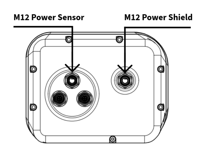
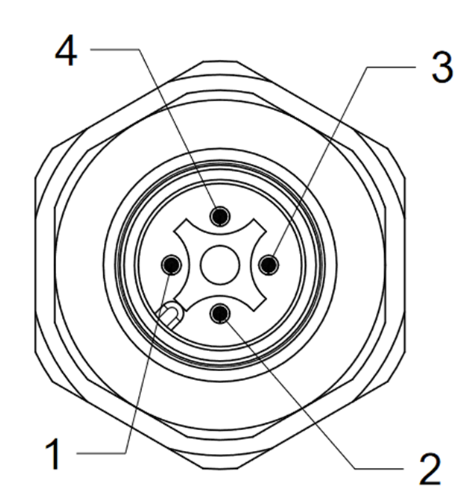
| Pin number | Function | Comment |
|---|---|---|
| 1 | Power | +9.5..+24V |
| 2 | Un-used | - |
| 3 | Ground | 0V |
| 4 | Un-used | - |